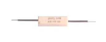
"SURE" BRAND WIRE WOUND RESISTOR - SCF
Ceramic Encased Axial Lead with Fusible Rating Wire Wound Resistor
Introduction:
'SURE' provides fusible resistor which fuse or blow if they are subjected to an abnormal spike of voltage / current. SCF Series is a low cost resistor fusible resistor which provides circuit protection for overload or component failure. The resistor will open quickly under continuous load and prevent circuit board from damage and hazards.
Features:
• High Power dissipation in small volume
• High surface insulation property
• Completely fire proof and welded construction
• Available in PCB type and capacitor type terminals
• Formed leads available on request
• Low inductance type available on request
• Long leads also available
General Specifications
DESCRIPTION
SCF03
SCF04
SCF06
SCF09
SCF12
SCF20
Resistance range, Series
And tolerance (1) + 10 % + 5 %
E24 Series
0.01Ω - 0.05Ω
0.06Ω - 100kΩ
Maximum dissipation at Tamb = 400c
03 W
04W
06 W
09 W
12 W
20 W
Maximum permissible voltage
(volts DC or RMS)
V =√ (Pn x R)
Insulation voltage
> 2000 V
Temperature coefficient. (2)
R < 10Ω: 0 to +600ppm/0c
Operating temperature
R >10 W: -100 to +150ppm/0c
- 550c to + 275 0c
Stability DR/Rmax after:
Lead, 1000 hours
Climate tests
Short time overload
+ 5.0% + 0.1Ω + 3.0% + 0.05Ω + 4.0% + 0.05Ω
(1) Tolerances, 1% and 3% available on request
(2) Temperature coefficient, 30, 50 and 90ppm/°C, available on request
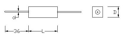
Mechanical Data
Table 1
TYPE
L
D
d
SCF03
15 + 1.5
7.5 + 0.8
0.81 + 0.03
SCF04
25 + 1.5
7.5 + 0.8
0.81 + 0.03
SCF06
25 + 1.5
9.5 + 0.8
0.81 + 0.03
SCF09
38 + 1.5
9.5 + 0.8
0.81 + 0.03
SCF12
38 + 1.5
11.0 + 0.8
0.81 + 0.03
SCF20
50 + 1.5
11.0 + 0.8
0.81 + 0.03
Construction
SCF: The resistor element is a resistive wire, which is wound, on ceramic rod. Tinned copper leads are connected to the caps by welding. The resistor body is housed in a rectangular ceramic case with a special inorganic potting which is non-flammable, will not melt even at high overloads and is resistant to most commonly used cleaning solvents and moisture.
Electrical Characteristics DERATING
The power that the resistor can dissipate depends on the operating temperature; see below
Fig - Maximum dissipation (Pmax) in percentage of rated power as a function of the ambient temperature (Tamb)
Applications:
The SCA Series is recommended for the use where occasional overload is upto 125% for long time [upto 2 Hrs.] are probable. This Series is also preferred for aesthetic value. The fusible resistors (SCF) are also available in this series.
Test and Requirements
Essentially all tests and requirements present in table below follow the schedule of IEC standard publication 60115-1, 60115-4 and 60068.
TEST
PROCEDURE
REQUIREMENTS
Insulation resistance
500 V (DC); during 1 minute
V-block method
Rins min 100 MW
Voltage proof on
insulation
1000 V (RMS); during
1 minute V-block method.
No breakdown or flashover
Temperature
Coefficient
Between
-550c at +2750c:
R < 10 W
R > 10W
0 to +600ppm/0c
+ 150 to - 100ppm/0c
Short time overload
5 times the rated wattage for 5 sec
DR/Rmax: + 2% +0.05W
Robustness of terminations:
Tensile all samples
Bending half number of samples
Torsion other half
Number of samples
Load 10N; 10 s
Load 5N; 4 x 900c
3 x 3600c in opposite
Directions
No visible damage
DR/Rmax; + 2% + 0.05W
Solderability
(after ageing)
16h at 155 0c, leads
Immersed in flux 600, leads immersed 2 mm for 2 + 0.5 s in a solder bath a 235 + 50c
Good tinning;
No damage
DR/Rmax; + 0.5% + 0.05W
Resistance to Soldering heat
Thermal shock; 3s, 35 0c;
6mm from body
DR/Rmax; + 4% + 0.05W
Rapid change of
temperature
30 minutes at-550c and 30 minutes at + 275 0c;
5 cycles
NOTE : Fusible resistors are not standard resistor types and each type of fusible resistor must be designed to suit a particular application.
Data required to design a fusible resistor are:
• The type you require -
Ceramic Encased or Axial Lead Type
• Resistance in ohms.
• Power rating in terms of watts.
• Tolerance.
• Fusing current - The current at which the resistor must fuse or blow.
• Fusing time - The duration within which the resistor must fuse or blow, on being subjected to the fusing current.
At SURE if no special data is provided, a fusible resistor can be made as per the following chart :
FUSING CHARACTERISTICS :
POWER
FUSING TIME
MAX
16 X Wattage
1 min
20 X Wattage
40 sec
24 X Wattage
30 sec
28 X Wattage
20 sec
32 X Wattage
15 sec
TYPICAL APPLICATIONS :
As mentioned previously a fusible resistor is a dual purpose component -
(a) In normal conditions it functions as a resistor.
(b) In high overload conditions it acts as a fuse/safety device.
In some countries all types of ceramic encased type resistors are wrongly called as fusible resistors. It must be clearly understood that fusible resistors are special purpose, specially designed resistors and are produced mainly in two configurations -
(a) Ceramic encased type (SCF) and
(b) Flame retardant silicone coated axial lead type. (SSF)